I have two Chinese Pixie kits that I've assembled. I think they are pretty interesting, from a QRP / tinkering stand-point.
Looking at the schematic below, where is the beat frequency coming from?
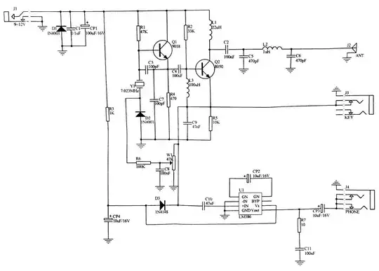
I know Q1 is part of the crystal oscillator and Q2 is essentially the power-amp during transmit, but what is mixing with the incoming signal to create the CW tone instead of the simple hissing you'd hear? I simply cannot see where this is happening. I do understand all of the other areas of the circuit (power supply area, keying, audio amp and low-pass filter on the antenna).
Pixie schematic
I'd like to do more tinkering with this, but before I do, I really would like a firm knowledge of what is acting as the BFO here.